-
Technology
-
Operation Mode of the Waste Treatment Plant (INTEC WS Series)
-
Operation Mode of the Synthesis Gas Plant Units (INTEC SG Series)
-
Operation Mode of the Power Generation Plant Units5 (INTEC PP-Series)
-
Process Features
-
Utilisable Input Materials
-
Plant Data
-
Quantities per Production Line
-
Concluding Remarks
-
Patents
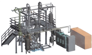
1. Technology
The INTEC Synthesis Gas Systems generate electrical energy to be fed-in to the public grid or to other industrial plants by thermal recovery of organic residues from waste of commerce and industry, health sector, agriculture and forestry, municipalities and other sectors (except toxic and hazardous residues).
Main plant components of the plant system are:
- Plant unit for waste sorting and conditioning (INTEC WS Series)
- Plant unit for the generation of synthesis gas (INTEC SG Series)
- Plant unit for the generation of electrical energy (INTEC PP Series)
- Steam Turbine Plant for the heat utilisation from the generators for the generation of additional electrical power
Main procedural steps are:
- Separation, conditioning and drying of the delivered waste.
- Generation of synthesis gas from conditioned waste with the patented INTEC Thermolytic Cracking Process (INTEC-TCP®).
- Combustion of the synthesis gas in gas Otto-engines as generator drives for electricity generation and waste heat recovery for power production with a Steam Turbine Plant.
Control of the entire plant system is conducted by a process guidance system (Siemens PCS7) which is designed for automatic operation. In addition, the entire system is equipped with a remote maintenance system that ensures operational safety 24 hours on 365 days a year. Key sensors and actuators are redundantly designed. The power supply for key plant components is secured by an uninterruptible power supply (UPS) and an emergency power supply.
1.A Operation Mode of the Waste Treatment Plant (INTEC WS Series)
The drawing layout shows various possibilities for the processing of the waste.
In the following, the method is first described, in which the drying of the waste is mainly carried out using exhaust heat from synthesis gas production and electricity generation.
In this case, the possible evaporation quantity and thus the degree of moisture of the refuse are limited since the supply of additional energy is to be avoided as far as possible.
If the amount of waste is greater than or equal to 30%, biological drying is required.
Whether only one or a combination of the two methods is used depends on the properties of the garbage which has to be processed.
The design parameters for the plant are determined by the garbage properties, the intended use of the final product and the size of the synthesis gas plant.
The garbage is delivered by truck.
The mass of the material delivered is collected via a vehicle balance before it is unloaded into the acceptance bunker.
The acceptance bunker is located in a closed processing hall.
Air sluices at the tipping points ensure that no unwanted odors escape.
The suctioned air then passes through the cleaning system.
The floor of the acceptance bunker consists of slotted concrete slabs, through which the leaking seepage can flow to the treatment system.
From here, the coarse crusher, which is protected by a bar strainer before oversize the waste components, is fed by means of a bunker crane.
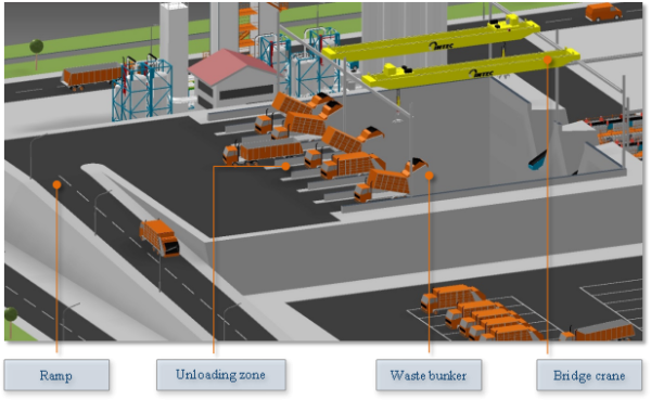
Illustration 1: Unloading zone and acceptance bunker
The subsequently following sieving units separate the material stream in a coarse and fine fraction. With a system of belt conveyors, the fine fraction is directly transported to the separators for ferrous and non-ferrous metals, glass and minerals to be discharged. The accordingly conditioned material stream is subsequently conveyed to a drying unit, where by means of heated air (residual heat from the gas- and electricity- generation) with a temperature of approx. 70 – 80 °C, the necessary residual moisture of approx. 10 – 15 % is achieved.
The coarse fraction is conveyed to the fine shredders and subsequently transported to the separate sorting lines. Analogous to the procedure with the fine fraction, the discharge of inorganic material and pre-drying is carried out.
The material streams from the dryers of one line are collected and conveyed to the respectively designated sieving unit. The fraction with a grain size < 35 mm serves as the input material for the reactors whilst the oversized material is re-fed to the fine shredding unit.
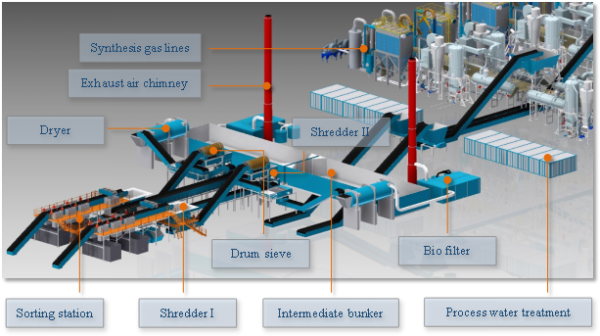
Illustration 2: Waste conditioning
For a moisture content of more than 30%, INTEC recommends the use of a mechanical-biological treatment plant for economic reasons.
The system offered by INTEC, as shown in the layout as item no. 17 contains all necessary premises and equipment for continuous plant operation
(see also separate MBT description).
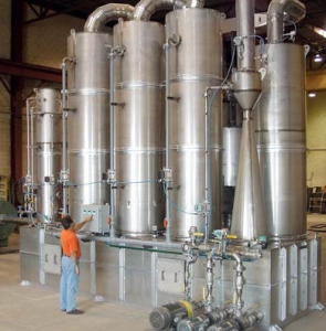
1.B Operation Mode of the Synthesis Gas Plant Units (INTEC SG Series)
The synthesis gas process serves the chemical and energetic conversion of substitute fuels and biomass into a synthesis gas in several process steps.
The produced synthesis gas with an average calorific value of 25,000 kJ / m³ can be used both for electricity generation in gas engines and turbines as well as for the production of process heat.
A synthesis gas plant is a modular system consisting of one or more basic lines corresponding to the selected size.
The main components of a base line are:
- Main Reactor
- Secondary reactor
- Crack reactors
- Scrubber
- Attendant facilities
Main reactor
The main reactor consists essentially of the entry zone, mixing chamber, high-temperature chamber, conversion chamber and heating envelope.
The substitute fuel generated in the INTEC processing plant is introduced into the reactor via the feed area into the upper mixing chamber. The fuel surrogate generated in the INTEC treatment plant is fed into the reactor via the feed area into the upper mixing chamber. In the mixing and high-temperature chamber of the main reactor, which is heated in a double jacket, the chemical conversion of the material fed into gaseous hydrocarbons takes place mainly. For this purpose, chemical processes in descending gasification are carried out in the chambered, pressurized apparatus at temperatures between 400 ° C. and 850 ° C. and with air closure. The material movement within the apparatus is effected by a screw.
Secondary reactors
The structure of the secondary reactors is similar to that of the main reactor.
The raw gas-coke mixture formed at the end of the main reactor is fed into the cascade-designed secondary reactors. Through a long residence time and high temperature, the complete conversion of the hydrocarbons takes place here and the raw gas flows through the respectively formed coke bed in the high-temperature zones, which lengthens the time of the conversion reaction. The material movement within the apparatus is effected by screws.
Crack reactors
The cracking reactor is a tubular, heated apparatus with a double-jacket design. It has an internal charge of zeolites, which serve as a catalyst in the cleavage of long-chain hydrocarbons.
The reactions occurring during cracking are very complex processes in which the relatively large molecules of the starting materials are catalytically decomposed into smaller and highly reactive fragments. The light oil vapour (low-boiling hydrocarbons) discharged from the gas scrubber is fed to the cracking reactor, heated and passed through the zeolite granules. The resulting cleavage products are conveyed in a controlled manner into the mixing chamber of the main reactor and here cause chemical reactions as an organic steam component with which the gas quantities which are to be generated can also be controlled.
Gas cleaning
The main components of the scrubber system are scrubbers, several pumps, heat exchangers and separators as well as a high pressure fan system. Gas purification is standardized as a five-stage process, in which the synthesis gas passes through several processes, which run at defined temperature levels by means of a pressure elevation stage. For gas washing, a working medium is conveyed in circulation through the apparatus which absorb condensates and pollutants. The medium, together with the bound substances, is passed through the separator, as well as the crackers and scrubbers, and purified.
In the first stage, tar, oil and dust particles are separated from the synthesis gas stream, which simultaneously cools the same.
The following steps are used to separate further hydrocarbons and pollutants.
Attendant facilities
The attendant facilities include the safety system and the wastewater treatment plant.
The safety system provides protection against gas overpressure in the event of an accident. The existing and still emerging synthesis gas is sent to the emergency flare via a short-circuit system and is combusted in a controlled manner.
The waste water treatment consists of a physico-biological system with activated sludge reactors and, if necessary, an additional disinfection by ozonation.
After passing through the plant, the wastewater can be discharged into the public network.
1.C Mode of the Power Generation Plant Units Operation
A gas engine system and waste heat recovery with steam turbine systems are used for generating electricity.
The synthesis gas, buffered in intermediary storage tanks, reaches the gas Otto-engines coupled with 10 kV generators via a compressor system. In case of identical voltage, the generated electrical energy can be directly fed-in to the medium-voltage grid.
In case of differing values, the voltage is transformed to the required value – if necessary, also to the high-voltage grid up to 110 kV.
The exhaust gas stream of the gas Otto-engines is led through the primary circuit of a waste heat steam boiler (heat exchanger).
The energy contained therein evaporates the working medium (water) in the secondary circuit of the waste heat steam boiler.
The steam drives the steam turbine connected to a generator of the post-generation plant (steam turbine system).
The electricity generated here is available to the consumers or the grid feed-in
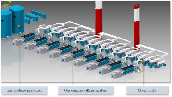
Illustration 3: Power generation from synthesis gas
2. Process Features
- Emission-free synthesis gas generation
- Low noise emission < 65 dB(A)
- Low soil sealing
- No polluted process waste water
- No build-up of dioxins, furans or flue-gases
- Complete processing in closed buildings
- Also the organics in polluted waste is converted into energy
|
|
- Low operating costs
- Modular and redundant plant design
- Adaptable to the infrastructure and requirements on-site
- High energy yield
- Low internal energy consumption (self-generated)
- Low consumption of operating supplies and water
|
|
|
- Closed systems of synthesis gas generation and treatment
- Low pressure operation in the areas of gas generation and conditioning
- Carbon conversion higher than 99 %
- High efficiency degree
- Modular design of the plant capacities
- Under-pressure operating mode in synthesis gas generation and treatment
|
|
- All safety installations and measures according to European and German Standards and Legislations
- Explosion protection, Fire prevention
- Emergency stop and power supply
- Lightning protection
- Noise protection
- Remote Maintenance system for more additional safety
|
|
Table 1: Process features
3. Utilisable Input Materials
- Paper, cardboard
- Cellulose
- Plastics
- Rubber
- Textiles
- Wood
- Biomass of any kind
|
|
- Oils and fats
- Paints and varnishes
- Tars and tar-containing wastes
- Resins and adhesives
- Bitumen and bitumen-containing waste
|
|
- Rejects, shredder-light fractions etc.
- Hospital waste (according to local legislation
- Sludge from waste water treatment (dried)
- Waste from private households
- Waste from forestry and agriculture
|
|
Table 2: Utilisable input materials
4. Plant Data
4.A Quantities per Production Line
- Reactor throughput: up to 3,3 t/h conditioned organic waste(including 10 m% residual moisture)
- Producible gas volume: 1,600 – 2,400 Nm³/h
- Energy amount (electrical)approx. 1.2 to 1.8 MWh/t conditioned waste
In dependence of the delivered waste composition, the necessary quantity of the waste to be delivered might considerably higher as the actual possible reactor throughput.
5. Concluding Remarks
The synthesis gas generation and utilisation is a multi-staged process and bases on the partial steps drying, de-gassing, gasification, gas scrubbing, gas combustion and electricity generation.
The application of the technology on the basis of the INTEC Thermolytic Cracking Process (INTEC-TCP®) allows a highly efficient utilisation of organic wastes for the generation of clean energy.
The control of the complete system is carried out by a process control system (Siemens PCS 7), designed for automated operation including remote maintenance. This ensures the operational liability 24 hours, 7 days a week on 365 days a year. Important sensors and actuators are redundantly designed. For essential plant components, the power supply is secured by an uninterruptible power supply (UPS) and an emergency power supply.
6. Patents
The technology, reactor and gasifier are secured by patents. The first patent was granted in December 2015.